System characteristics
A wireless communication system that transmits digital information from an information source to an information transmission destination can generally perform a model analysis of the communication system similar to FIG. The communication mode of the communication system can be divided into a transposition mode and an encoding mode, but the non-contact IC card communication system is not the case. The information processed by the non-contact IC card system is mainly high-sensitivity digital data related to finance and personal privacy. No errors are allowed in the way, and it is required to reach the level of error free.
Although the data transmission distance d of the non-contact IC communication system is only tens of cm and the transmission wavelength is as high as 2.2 m (13.56 MHz), d<λ<2π is established, which means that the non-contact IC card system uses the electromagnetic bonding field. Digital finance and personal privacy data communication are carried out. However, this method is very easy to cause communication quality due to various factors such as changes in impedance such as impedance.
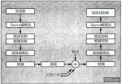
Figure 1 Communication system operation mode
Fig. 2 shows the operation principle of the non-contact IC card reader/writer (RW: Read & Writer). As shown in the figure, the non-contact IC card itself has no power supply, so the RW must supply communication power to the IC card. The RW and loop antennas, that is, the antennas of the IC cards, become electromagnetically coupled. The RW supplies power to the IC card using a 13.56 MHz transmission wave.
At this time, if RW transmits the data to the IC card, RW transmits an ASK (amplitude change) signal of about 10% to the IC card, and the IC card detects the signal and converts it into data; otherwise, if the data is transmitted from the IC card In RW, the IC card becomes the state of receiving the unadjusted signal from the RW, and then the load change is generated by the tone changer in the IC card, and the RW regards the load change as a self loop antenna, that is, the current and voltage change of the antenna of the RW and Data polyphony. Table 1 shows the main specifications of the physical and data link layers of FeilCa.
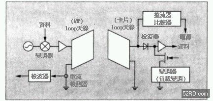
Figure 2 RW action principle
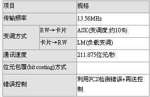
Table 1 Specifications of the physical layer and the data link layer
Next, we will introduce techniques related to how to achieve "completely error-free" circuit quality and error control. The powerful error correction technology in recent years has enabled many completely error-free requirements to be realized. Since the packet length of the contactless IC card communication system is as high as several hundred bits, the error correction effect is almost limited to random error. Range, theoretically, if a better bit error rate can be maintained, it will be more practical than using low coding efficiency and bad correction code. According to this, the researchers finally decided to adopt a low redundancy length and can detect the error detection code. In the hybrid mode of re-sending control, in fact, the traditional FeiluCa also follows the above structure for error relief and re-delivery control.
However, the bit error rate of the loop in the above manner is deteriorated, and the number of retransmissions is greatly increased. As a result, the communication success rate of the non-contact IC card communication system is deteriorated. For example, when the packet length is 256 and retransmission is performed twice, Obtain a communication error rate of 10-8, and the bit error rate of the loop must be lower than 10-5. At this time, if the ASK non-synchronous detection obtains a bit error rate of 10-5, the S/N ratio needs about 15 dB, so To ensure the expected goals of RW. The key to realizing the target value of the above bit error rate is how to deal with the change of impedance characteristics. The specific contents are:
‧Measures for changes in characteristics of non-contact IC cards ‧Adaptability of RW setting environment
Non-contact IC cards are characterized by no shape restrictions. Therefore, in recent years, even watches and list bands with built-in non-contact IC chips have appeared. In view of this, the future is bound to be extended to mobile phones and other fields, but RW Widespread application of RW compatibility, how to identify multiple non-contact IC cards at the same time, how to design complex RW without mutual interference, etc. become an important issue, that is, the following problems must be overcome in the future:
‧Support the adaptability of diverse media and the surrounding environment ‧The ability to identify multiple non-contact IC cards ‧Inhibit mutual interference between complex RW
Countermeasure technology
Figure 3 is an example of the effect of media characteristics on the contactless IC card access system. As shown in the figure, it is the distance between the non-contact IC card-RW, and the signal strength to the complex number between the RW and the non-contact IC card. The interaction relationship between the card resonance frequency fc variables, it can be seen from the figure that the communication characteristics of fc are relatively large, especially the characteristics of fc=15MHz. When the distance between the non-contact IC card-RW is d=10mm, the signal strength is almost Close to zero cross.
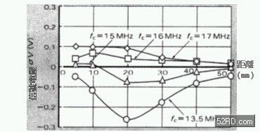
Figure 3 Relationship between communication distance and signal strength
Fig. 4 is a result of analysis of the influence of the impedance of the RW antenna when the sheet metal component pair is placed in the vicinity of the RW antenna. It can be seen that since the eddy current flows inside the sheet metal component, the impedance component decreases and the resonance frequency moves toward the high point. .
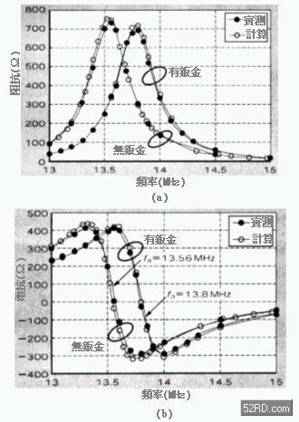
Figure 4 Effect of sheet metal components on RW antenna
Mobile Flipchart U Stand,Magnetic Whiteboard Sheets For Board,Magnetic Glass Flipchart Easel Board,Magnetic Flipchart Easel Board
Dongguan Aoxing Audio Visual Equipment CO.,Ltd , https://www.aoxingboard.com