1 Introduction
Surface mount technology (SMT) has become the most common technology in today's electronic assembly technologies. Solder paste printing is one of the key processes in the SMT basic process, and its quality directly affects the quality and efficiency of SMT assembly. With the high density of electronic assemblies and the miniaturization of components, fine-pitch leads and lead-free processes place higher demands on solder paste printing. In order to ensure product quality and formulate a reasonable printing process, it is necessary to discuss the solder paste printing technology and process parameter settings.
2 Solder Paste Printing Technology
In SMT production, there are two kinds of techniques for depositing solder paste on the PCB pad: one is a printing technology mainly based on screen and metal stencil printing templates, and it is a solder paste coating method widely used in industrial manufacturing. Suitable for mass production. Another injection-coating technique for applying solder paste to an injection system is suitable for small-volume production. This system is controlled by a computer and can accurately deposit solder paste, which can prevent solder paste from being wasted.
2.1 Screen Printing Technology
The screen printing mechanism consists of a PCB positioning system, a doctor blade system and a screen plate. The stencil is a key component of the screen printing machine and consists of a frame, a screen, and a mask pattern. The mask pattern is generally formed on the screen by a suitable method, and the screen is tightened on the screen frame.
Common frame materials include wood, aluminum alloys, and stainless steel. In the premise of meeting the strength requirements, light alloys should be selected as far as possible in order to facilitate the operation. According to the stretching method, the frame has two types of fixed frame and self-tensioned frame. The fixed net frame is fixed on the net frame by a common adhesive fixing method; the self-tensioning net frame is stretched to the net frame by means of a stretch net machine, so that the tensioned position of the silk net frame and the net frame form an integral whole. With the help of "screw adjustment" or "stick frame" self-tensioning net, it is suitable for occasions with many varieties and less batch printing.
Screen printing is commonly used to etch mesh/latex stencils. The commonly used materials for screens are stainless steel or monofilament polymeric resins. When used, apply a layer of sensitizing emulsion to the screen to dry it into a photosensitive film. The negative film is then placed against the photosensitive film and exposed to ultraviolet light. The exposed portion becomes a permanent coating, and the unexposed portion is dissolved by the developer. In this way, a leak is formed in the adhesive portion where the solder paste is to be deposited and dried to form a screen. The diameter of the wire and the size of the opening depend on the number of meshes and is usually 80. The diameter of the filament and the thickness of the latex mainly determine the thickness of the deposited solder paste. In general, the screen is only suitable for applications where the solder joint height is 300 μm or more. It is suitable for solder pastes with a viscosity of 400-600 Pa·s. The scraper uses a rubber or polyimide tree scraper with a hardness of 70-90. The average size of the alloy powder particles in the paste should not be larger than 1/5 of the screen mesh size.
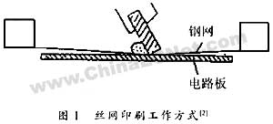
Screen printing for non-contact printing, prone to solder paste leakage defects (as shown in Figure 2). Screen printing usually requires slower speeds than stencil printing, with a larger squeegee gap: At the same time, a lower viscosity paste should be used for ease of printing. In addition, during the printing, the screen and the work stand should be adjusted in parallel to maintain a 0.5 mm scratch clearance.
2.2 Stencil Printing Technology
Template stencil printing is a direct printing technology. It uses metal stencils instead of screens in screen printing machines. The so-called template is a chemical method on a piece of metal or laser engraving method, unlike the screen hole to prevent the flow of solder paste, so the template can pass 100% of the solder paste, and the screen can only make about 50 % solder paste passed. According to the etching material, the template can be divided into a selective flexible metal template and an all-metal template.
Fine-pitch solder paste printing usually uses metal stencil printing, so the stencil aperture controls the solder paste on the pad and the missing print quality. The thickness of the stencil determines the thickness of the printed solder paste. The opening size of the stencil determines the area and shape of the solder paste. Thicker stencils are not conducive to solder paste release, and are also prone to bridging due to thick solder paste. Too little solder paste in the template area affects soldering quality.
In general, the template is only suitable for applications where the solder joint height is within 100 to 300 μm. It is suitable for solder paste with a viscosity of 400 to 1200 Pa·s (600 to 800 Pa·s for the pitch and 800 to 1200 Pa·s for the fine pitch). The average size of the alloy powder particles should not be greater than 1/3 of the thickness and width of the template. In order to avoid deformation and wear of the blade tip, it is better to use a harder material such as a metal blade or a rubber or polyimide resin blade with a hardness of 90.
The template aperture ratio refers to the ratio of width to thickness, ie: W/T, typically 1.5:1. For the CSP and other graphics, the area ratio (AR) must be used, as shown in Figure 3. The value is generally greater than 0.66, and the solder paste release rate can reach more than 85%. The perfect solder paste deposit should have exactly the same shape as the template opening, ie A=D, H=T or 2/3A. Where A is the solder paste diameter, D is the opening diameter, T is the template thickness, and H is the solder paste thickness. Fig. 4 shows the relationship between the rate of release of solder paste and the area ratio. In order to increase the release rate of solder paste, the aperture ratio can be increased by increasing the width of the opening or decreasing the thickness. Alternatively, the template technology with a smooth opening wall can be used.
Compared with screen printing, stencil printing is more complicated and costly to process, but it has many advantages, such as insensitivity to solder paste particle size, difficulty in clogging, wide range of paste viscosity, uniform printing, clear graphics, stability, and long-term storage. They are very durable and have a life expectancy of approximately 25 times that of wire mesh, making them suitable for high-volume production and assembly of high-density, multi-lead, fine-pitch products.
3 stencil printing process
Taking stencil printing as an example, the solder paste printing process is as shown in FIG. 5 , which is divided into two parts: pressing the solder paste into the opening portion of the printing template and moving the solder paste to the substrate pad. The setting and adjustment of printing process parameters play a very important role in the printing quality.
3.1 Press the solder paste into the opening part of the printing plate
FIG. 6 shows the process of pressing the solder paste into the opening portion of the printing template, and the rotation of the solder paste plays a significant role. When the solder paste is moved by the squeegee, frictional force is exerted between the solder paste and the printing template surface, and the frictional force is opposite to the moving direction of the solder paste. The solder paste will rotate under this frictional force, that is, rolling phenomenon. Once the rolling phenomenon occurs, the solder paste will often hit the front of the blade, change direction, and generate pressure in the front of the blade. This pressure is the force that presses the solder paste into the printing template. At the same time, by rolling, the direction in which the scraper is lifted is also powerful. Therefore, in order to achieve correct printing, it is necessary to appropriately control the force for pressing the solder paste into the opening portion of the printing template and the force for lifting the blade.
(1) The optimal setting of the blade speed and the blade angle
Squeegee speed and scraper angle are two basic factors controlling the press-in force (see Figure 7). The best setting for the so-called squeegee speed is to set the solder paste so that it does not slide on the printing plate, and the setting of the rolling movement. Squeegee speed can vary from 10 to 150 mm/s, typically 25 to 50 mm/s. OFPs with pitch less than 0.5 mm are 20 to 30 mm/s, and ultrafine and fine pitches are 10 to 20 mm/s. s, generally 12.7 mm/s. It is noteworthy that, due to the large pitch printing or large pressure printing of the rubber blade, the deformation will result in scratches resulting in insufficient printing volume. Therefore, the speed of the rubber blade is higher than that of the metal blade, which is generally close to twice its value.
If the squeegee speed is high, the solder paste impacts the front of the squeegee at a relatively high speed, resulting in a large force. Considering the time when the blade passes through the opening portion, that is, the time for pressing the solder paste is short, the final result is that the pressure applied to the entire opening portion during printing is constant, that is, the amount of solder paste pressed into the opening portion. Not changed. In general, the printing speed is low and the filling is good, and no drag is generated after the squeegee as shown in FIG. 8 .
The distribution of the pressure generated by the front of the blade from the computer is shown in Figure 9. The pressure generated in the front of the doctor blade is distributed in a very narrow range of only 2 to 3 mm before the doctor blade, so it can be said that the effect of the doctor blade angle and its change on the generated pressure is only at the angle of the front part of the part.
The squeegee angle is generally controlled at 45° to 75°, so that the transfer coefficient = transfer depth/limit pressure represents the relationship between the squeegee angle and the limit printing pressure. According to the test results, the optimum printing effect and transferability can be obtained when the optimum setting of the scraper is in the range of 60°C to 70°C, with appropriate printing pressure and speed. Scraper angle is too small, rolling and filling, but prone to leakage, is generally used for reflow and fine pitch stencil printing, in order to increase the amount of solder paste.
(2) Optimal setting of printing pressure
The force applied to the blade is referred to as the printing pressure. If the force is too large, the front of the blade will be deformed, and the angle of the blade, which plays an important role in the press-in force, will be affected. FIG. 10 shows a phenomenon in which the front of the blade is lifted during the rolling of the solder paste. If the front of the blade is lifted during the rolling of the solder paste, a gap will occur between the front of the blade and the printing plate, and solder paste will remain on the printing plate. The printing pressure should generally be the same as the pressure generated by rolling. Generally, it can be set in the range of 5 to 100 MPa. The occurrence of collapsed cores and leakage defects is usually 10-30 MPa. In addition, since the force generated by rolling changes with the amount of the supplied solder paste, the operator needs to adjust the optimum value appropriately.
3.2 The process of moving the solder paste to the substrate pad
In order to move the solder paste from the opening portion of the printing plate to the pad of the printed circuit board, it is necessary to fix the printing plate to press the printed circuit board in the vertical direction. The force generated at this time acts on the pad and the substrate. The adhesive force between the paste and the frictional force acting between the printed board surface and the solder paste when the solder paste filled in the opening portion is moved. When this frictional force is greater than the adhesive force acting between the substrate pad and the solder paste, the solder paste does not move in the opening portion and printing cannot be performed. In contrast, when the friction is small, the solder paste moves smoothly. It can be seen that in this process, the design of the opening portion of the printing template and the setting of the demoulding speed are very important.
(1) The best design of the template
From the printing mechanism, the best design requirements of the template are as follows: 1 The opening area of ​​the template is larger than the area of ​​the inner wall of the opening, so that the adhesion force of the welding surface is greater than the friction; 2 The wall surface of the opening should be as smooth as possible, taking into account the detachment It is designed to have an "8" shape (in the case of a laser template, if it is machined from the substrate side, it will naturally become this shape).
(2) Optimal setting of demoulding speed
When the substrate is lowered, the printing template becomes large due to the adhesive force of the solder paste to form a deflection. If the deflection of the printing plate becomes larger, the template will return to its original position due to the elasticity of the deflection. As a result, at a certain position, the template quickly resets due to its elastic force, lifts the solder paste around and forms an extremely raised printing shape at both ends, and the lifting height is proportional to the deflection of the template. In severe cases, the solder paste is also scraped off so that the solder paste remains in the opening portion. FIG. 11 is a graph showing the relation between the demolding speed and the print quality. Normally, the demolding speed is set to 0.3 to 3 mm/s. The gap between the template and the PCB during printing is less than 0.5 mm, the demoulding distance is generally 3 mm, the specific detachment speed is shown in Table 1, and the actual stripping speed
Fast Sales Product Display Rack
Fast Sales Product Display Rack,Drinks Advertise Display Stand,Cans Drink Display Stand,Supermarket Display Rack For Heavy Product
Dongguan Display Leader Co., Ltd , https://www.displayonestop.com